Theory and Operation of Capacitors
Capacitors are components constructed by placing two conductive plates (usually metal) in close
proximity with each other. There are many different styles of capacitor
construction, each one suited for particular ratings and purposes.
For very small capacitors, two circular plates sandwiching an insulating
material will suffice. For larger capacitor values, the "plates" may be
strips of metal foil, sandwiched around a flexible insulating medium
and rolled up for compactness.
The highest capacitance values are
obtained by using a microscopic-thickness layer of insulating oxide
separating two conductive surfaces. In any case, though, the general
idea is the same: two conductors, separated by an insulator.
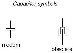
The schematic symbol for a capacitor is quite simple, being little
more than two short, parallel lines (representing the plates) separated
by a gap.
Wires attach to the respective plates for connection to other
components. An older, obsolete schematic symbol for capacitors showed
interleaved plates, which is actually a more accurate way of
representing the real construction of most capacitors:
When a voltage is applied across the two plates of a capacitor, a concentrated field flux is created between them, allowing a significant difference of free electrons (a charge) to develop between the two plates:

As the electric field is established by the applied voltage, extra
free electrons are forced to collect on the negative conductor, while
free electrons are "robbed" from the positive conductor.
This differential charge equates to a storage of energy in the capacitor,
representing the potential charge of the electrons between the two
plates. The greater the difference of electrons on opposing plates of a
capacitor, the greater the field flux, and the greater "charge" of
energy the capacitor will store.
Because capacitors store the potential energy of accumulated
electrons in the form of an electric field, they behave quite
differently than resistors (which simply dissipate energy in the form
of heat) in a circuit.
Energy storage in a capacitor is a function of
the voltage between the plates, as well as other factors which we will
discuss later in this chapter.
A capacitor's ability to store energy as
a function of voltage (potential difference between the two leads)
results in a tendency to try to maintain voltage at a constant level.
In other words, capacitors tend to resist changes in voltage drop.
When voltage across a capacitor is increased or decreased, the capacitor "resists" the change by drawing current from or supplying current to the source of the voltage change, in opposition to the change.
To store more energy in a capacitor, the voltage across it must be
increased. This means that more electrons must be added to the (-)
plate and more taken away from the (+) plate, necessitating a current
in that direction.
Conversely, to release energy from a capacitor, the
voltage across it must be decreased. This means some of the excess
electrons on the (-) plate must be returned to the (+) plate,
necessitating a current in the other direction.
Just as Isaac Newton's first Law of Motion ("an object in motion tends
to stay in motion; an object at rest tends to stay at rest") describes
the tendency of a mass to oppose changes in velocity, we can state a
capacitor's tendency to oppose changes in voltage as such: "A charged
capacitor tends to stay charged; a discharged capacitor tends to stay
discharged."
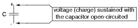
Hypothetically, a capacitor left untouched will
indefinitely maintain whatever state of voltage charge that its been
left it. Only an outside source (or drain) of current can alter the
voltage charge stored by a perfect capacitor:
Practically speaking, however, capacitors will eventually lose their stored voltage charges due to internal leakage paths for electrons to flow from one plate to the other. Depending on the specific type of capacitor, the time it takes for a stored voltage charge to self-dissipate can be a long time (several years with the capacitor sitting on a shelf!).
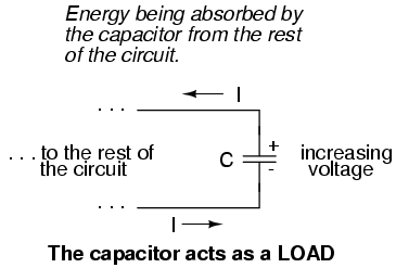
When the voltage across a capacitor is increased, it draws current from the rest of the circuit, acting as a power load. In this condition the capacitor is said to be charging, because there is an increasing amount of energy being stored in its electric field. Note the direction of electron current with regard to the voltage polarity:
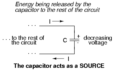
Conversely, when the voltage across a capacitor is decreased, the capacitor supplies current to the rest of the circuit, acting as a power source. In this condition the capacitor is said to be discharging. Its store of energy -- held in the electric field -- is decreasing now as energy is released to the rest of the circuit. Note the direction of electron current with regard to the voltage polarity:
If a source of voltage is suddenly applied to an uncharged capacitor
(a sudden increase of voltage), the capacitor will draw current from
that source, absorbing energy from it, until the capacitor's voltage
equals that of the source.
Once the capacitor voltage reached this
final (charged) state, its current decays to zero. Conversely, if a
load resistance is connected to a charged capacitor, the capacitor will
supply current to the load, until it has released all its stored energy
and its voltage decays to zero.
Once the capacitor voltage reaches this
final (discharged) state, its current decays to zero. In their ability
to be charged and discharged, capacitors can be thought of as acting
somewhat like secondary-cell batteries.
The choice of insulating material between the plates, as was
mentioned before, has a great impact upon how much field flux (and
therefore how much charge) will develop with any given amount of
voltage applied across the plates.
Because of the role of this
insulating material in affecting field flux, it has a special name: dielectric.
Not all dielectric materials are equal: the extent to which materials
inhibit or encourage the formation of electric field flux is called the
permittivity of the dielectric.
The measure of a capacitor's ability to store energy for a given amount of voltage drop is called capacitance. Not surprisingly, capacitance is also a measure of the intensity of opposition to changes in voltage (exactly how much current it will produce for a given rate of change in voltage). Capacitance is symbolically denoted with a capital "C," and is measured in the unit of the Farad, abbreviated as "F."
Convention, for some odd reason, has favored the metric prefix "micro" in the measurement of large capacitances, and so many capacitors are rated in terms of confusingly large microFarad values: for example, one large capacitor I have seen was rated 330,000 microFarads!! Why not state it as 330 milliFarads? I don't know.
An obsolete name for a capacitor is condenser or condensor. These terms are not used in any new books or schematic diagrams (to my knowledge), but they might be encountered in older electronics literature. Perhaps the most well-known usage for the term "condenser" is in automotive engineering, where a small capacitor called by that name was used to mitigate excessive sparking across the switch contacts (called "points") in electromechanical ignition systems.
- REVIEW:
- Capacitors react against changes in voltage by supplying or drawing current in the direction necessary to oppose the change.
- When a capacitor is faced with an increasing voltage, it acts as a load: drawing current as it absorbs energy (current going in the negative side and out the positive side, like a resistor).
- When a capacitor is faced with a decreasing voltage, it acts as a source: supplying current as it releases stored energy (current going out the negative side and in the positive side, like a battery).
- The ability of a capacitor to store energy in the form of an electric field (and consequently to oppose changes in voltage) is called capacitance. It is measured in the unit of the Farad (F).
- Capacitors used to be commonly known by another term: condenser (alternatively spelled "condensor").
Factors affecting capacitance
There are three basic factors of capacitor construction determining the amount of capacitance created. These factors all dictate capacitance by affecting how much electric field flux (relative difference of electrons between plates) will develop for a given amount of electric field force (voltage between the two plates):
PLATE AREA: All other factors being equal, greater plate area gives greater capacitance; less plate area gives less capacitance.
Explanation: Larger plate area results in more field flux (charge collected on the plates) for a given field force (voltage across the plates).
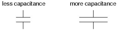
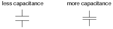
PLATE SPACING: All other factors being equal, further plate spacing gives less capacitance; closer plate spacing gives greater capacitance.
Explanation: Closer spacing results in a greater field force (voltage across the capacitor divided by the distance between the plates), which results in a greater field flux (charge collected on the plates) for any given voltage applied across the plates.
DIELECTRIC MATERIAL: All other factors being equal, greater permittivity of the dielectric gives greater capacitance; less permittivity of the dielectric gives less capacitance.
Explanation: Although its complicated to explain, some materials offer less opposition to field flux for a given amount of field force. Materials with a greater permittivity allow for more field flux (offer less opposition), and thus a greater collected charge, for any given amount of field force (applied voltage).
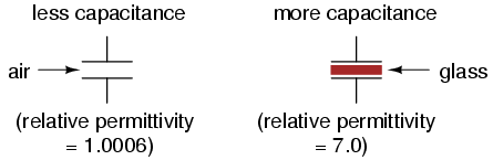
"Relative" permittivity means the permittivity of a material, relative to that of a pure vacuum. The greater the number, the greater the permittivity of the material. Glass, for instance, with a relative permittivity of 7, has seven times the permittivity of a pure vacuum, and consequently will allow for the establishment of an electric field flux seven times stronger than that of a vacuum, all other factors being equal.
The following is a table listing the relative permittivities (also known as the "dielectric constant") of various common substances:
Material        Relative permittivity (dielectric constant)
============================================================
Vacuum ------------------------- 1.0000
Air ---------------------------- 1.0006
PTFE, FEP ("Teflon") ----------- 2.0
Polypropylene ------------------ 2.20 to 2.28
ABS resin ---------------------- 2.4 to 3.2
Polystyrene -------------------- 2.45 to 4.0
Waxed paper -------------------- 2.5
Transformer oil ---------------- 2.5 to 4
Hard Rubber -------------------- 2.5 to 4.80
Wood (Oak) --------------------- 3.3
Silicones ---------------------- 3.4 to 4.3
Bakelite ----------------------- 3.5 to 6.0
Quartz, fused ------------------ 3.8
Wood (Maple) ------------------- 4.4
Glass -------------------------- 4.9 to 7.5
Castor oil --------------------- 5.0
Wood (Birch) ------------------- 5.2
Mica, muscovite ---------------- 5.0 to 8.7
Glass-bonded mica -------------- 6.3 to 9.3
Porcelain, Steatite ------------ 6.5
Alumina ------------------------ 8.0 to 10.0
Distilled water ---------------- 80.0
Barium-strontium-titanite ------ 7500
Series and parallel capacitors
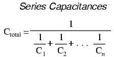
When capacitors are connected in series, the total capacitance is less than any one of the series capacitors' individual capacitances. If two or more capacitors are connected in series, the overall effect is that of a single (equivalent) capacitor having the sum total of the plate spacings of the individual capacitors. As we've just seen, an increase in plate spacing, with all other factors unchanged, results in decreased capacitance.
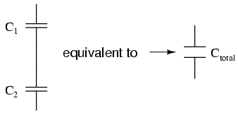
Thus, the total capacitance is less than any one of the individual capacitors' capacitances. The formula for calculating the series total capacitance is the same form as for calculating parallel resistances:
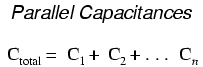
When capacitors are connected in parallel, the total capacitance is the sum of the individual capacitors' capacitances. If two or more capacitors are connected in parallel, the overall effect is that of a single equivalent capacitor having the sum total of the plate areas of the individual capacitors. As we've just seen, an increase in plate area, with all other factors unchanged, results in increased capacitance.
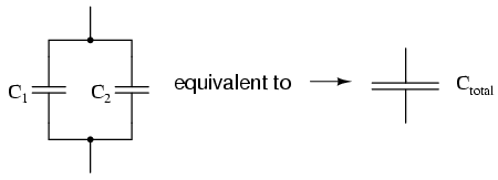
Thus, the total capacitance is more than any one of the individual capacitors' capacitances. The formula for calculating the parallel total capacitance is the same form as for calculating series resistances:
As you will no doubt notice, this is exactly opposite of the phenomenon exhibited by resistors. With resistors, series connections result in additive values while parallel connections result in diminished values. With capacitors, its the reverse: parallel connections result in additive values while series connections result in diminished values.
- REVIEW:
- Capacitances diminish in series.
- Capacitances add in parallel.
Practical considerations
Capacitors, like all electrical components, have limitations which must be respected for the sake of reliability and proper circuit operation.
Working voltage: Since capacitors are nothing more than two conductors separated by an insulator (the dielectric), you must pay attention to the maximum voltage allowed across it. If too much voltage is applied, the "breakdown" rating of the dielectric material may be exceeded, resulting in the capacitor internally short-circuiting.
Polarity: Some capacitors are manufactured so they can only tolerate applied voltage in one polarity but not the other. This is due to their construction: the dielectric is a microscopically thin layer of insulation deposited on one of the plates by a DC voltage during manufacture. These are called electrolytic capacitors, and their polarity is clearly marked.
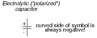
Reversing voltage polarity to an electrolytic capacitor may result in the destruction of that super-thin dielectric layer, thus ruining the device. However, the thinness of that dielectric permits extremely high values of capacitance in a relatively small package size. For the same reason, electrolytic capacitors tend to be low in voltage rating as compared with other types of capacitor construction.
Equivalent circuit: Since the plates in a capacitor have some resistance, and since no dielectric is a perfect insulator, there is no such thing as a "perfect" capacitor. In real life, a capacitor has both a series resistance and a parallel (leakage) resistance interacting with its purely capacitive characteristics:
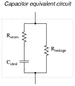
Fortunately, it is relatively easy to manufacture capacitors with very small series resistances and very high leakage resistances!
Physical Size: For most applications in electronics, minimum
size is the goal for component engineering. The smaller components can
be made, the more circuitry can be built into a smaller package, and
usually weight is saved as well.
With capacitors, there are two major
limiting factors to the minimum size of a unit: working voltage and
capacitance. And these two factors tend to be in opposition to each
other. For any given choice in dielectric materials, the only way to
increase the voltage rating of a capacitor is to increase the thickness
of the dielectric.
However, as we have seen, this has the effect of
decreasing capacitance. Capacitance can be brought back up by
increasing plate area. but this makes for a larger unit. This is why
you cannot judge a capacitor's rating in Farads simply by size.
A capacitor of any given size may be relatively high in capacitance and
low in working voltage, vice versa, or some compromise between the two
extremes. Take the following two photographs for example:
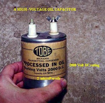
This is a fairly large capacitor in physical size, but it has quite
a low capacitance value: only 2 uF. However, its working voltage is
quite high: 2000 volts! If this capacitor were re-engineered to have a
thinner layer of dielectric between its plates, at least a hundredfold
increase in capacitance might be achievable, but at a cost of
significantly lowering its working voltage. Compare the above
photograph with the one below.
The capacitor shown in the lower picture
is an electrolytic unit, similar in size to the one above, but with very different values of capacitance and working voltage:
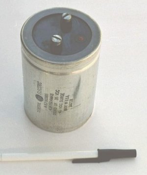
The thinner dielectric layer gives it a much greater capacitance (20,000 uF) and a drastically reduced working voltage (35 volts continuous, 45 volts intermittent).
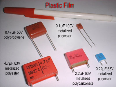
Here are some samples of different capacitor types, all smaller than the units shown previously:
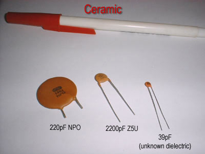
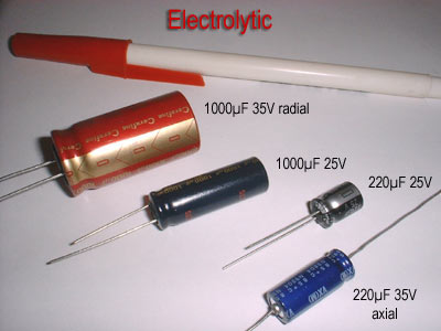
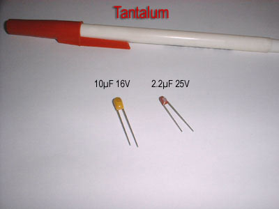
The electrolytic and tantalum capacitors are polarized
(polarity sensitive), and are always labeled as such. The electrolytic
units have their negative (-) leads distinguished by arrow symbols on
their cases. Some polarized capacitors have their polarity designated
by marking the positive terminal.
The large, 20,000 uF electrolytic
unit shown in the upright position has its positive (+) terminal
labeled with a "plus" mark. Ceramic, mylar, plastic film, and air
capacitors do not have polarity markings, because those types are nonpolarized (they are not polarity sensitive).
Published under the terms and conditions of the Creative Commons Attribution License
Modified by Lewis Loflin
Original URL http://www.allaboutcircuits.com/ (Modified)
Copyright 1999-2000 Michael Stutz stutz@dsl.org
- Constant Current Source Theory Testing
- Review Ohm's Law for Trouble-Shooting CCS Circuits
- Arduino Power Magnetic Driver Board for Stepper Motors
- Arduino Controlled Power Constant Current Source
- Related to above:
- Using a Unipolar Stepper Motor with a Arduino
- ULN2003A Darlington Transistor Array with Circuit Examples
- Tutorial Using TIP120 and TIP125 Power Darlington Transistors
- YouTube
- ULN2003A Transistor Array with Arduino
- Arduino Stepper Motor Control
- Using the TIP120 & TIP125 Darlington Transistors with Arduino
- Comparator Circuits:
- Comparator Theory Circuits Tutorial
- Comparator Hysteresis and Schmitt Triggers
- Voltage Comparator Information And Circuits
- Looking at Window Comparator Circuits
- Analog Battery Charger Uses Comparators
- YouTube:
- Comparator Circuits Introduction
- Photo Detector Devices:
- LM334 CCS Circuits with Thermistors, Photocells
- Photodiode Circuits Operation and Uses
- Photodiode Op-Amp Circuits Tutorial
- Photo Voltaic Tutorial MOSFET Output Solid State Relays
- YouTube:
- Photodiodes and How they Work
- Photodiode Op-Amp Circuits
- Using Photovoltaic MOSFET Drivers
- Digital Circuits:
- Simple Schmitt Trigger SN74HC14 Square Wave Generator
- Introduction to RC Differentiator Circuits and Uses
- SN74HC14 Square Wave Generator uses SN7476 JK Flip-Flop
- Three Output Pulse Generator Circuit for Digital Circuits
- Astable CD4047 Geiger Counter Power Supply
- CD4047 Monostable Multivibrator Circuit
- Basic TTL Tri-State Buffer Circuit Examples
- Tutorial NOR Gate SR Latch Circuits
- Tutorial NAND Gate SR Latch Circuit
- Tutorial OR-NOR Circuits Including Monostable Multivibrator
- Brief Tutorial of XOR and XNOR Logic Gates
- LM555-NE555 One-Shot Multivibrator AC Power Control
- YouTube:
- Three Output Digital Pulse Generator
- Test Power MOSFET Transistors, IGBTs Results, Observations
- High current TTL MOSFET Driver Circuit
- Insulated Gate Bipolar Transistor IGBT Circuits
- Optocouplers for TTL-CMOS Logic Level Shifting
- Light Activated SCR Based Optocouplers Circuit Examples
- Bidirectional Solid State Relay Circuits
- Build High Power MOSFET Bidirectional Switch Relay
- Digital Circuits
- Basic TTL Tri-State Buffer Circuit Examples
- Tutorial NOR Gate SR Latch Circuits
- Tutorial NAND Gate SR Latch Circuit
Other Circuits
- Hall Effect Magnetic Switches and Sensors
- Transistor-Zener Diode Regulator Circuits
- Build an Adjustable 0-34 volt power supply with the LM317
- Coils for Highly Selective Crystal Radio
- Neon (NE-2) Circuits You Can Build
- Understanding Xenon Flashtubes and Circuits