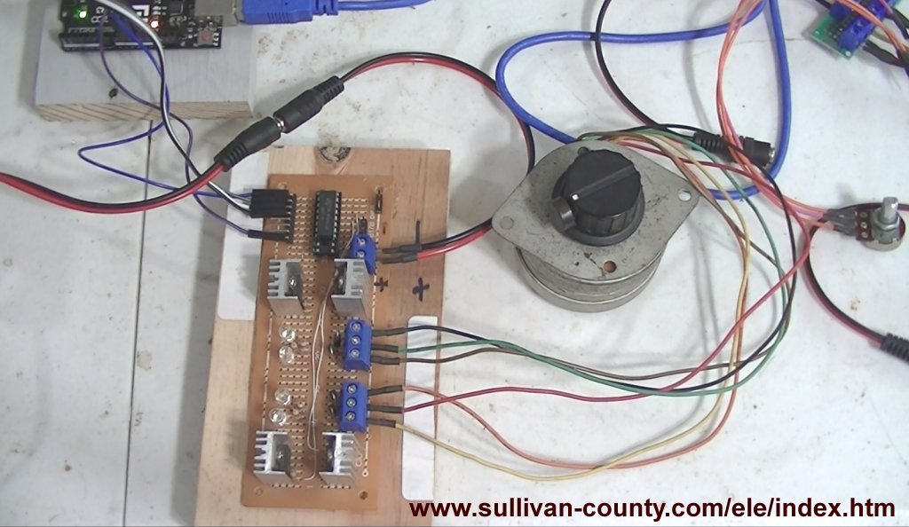
Fig. 1 Arduino with unipolar stepper driver control board.
Arduino Power Magnetic Driver Power Board
by Lewis Loflin
Note: click on any image for larger view.
This consists of two parts. The diagram of the driver board is self-explanatory. I use the open-collector ULN2003A to turn on a PNP transistor Vcc switch.
I use four TIP125 power Darlington transistors. They are rated at 5 amps at 60-volts. I use this to drive a unipolar stepper motor.
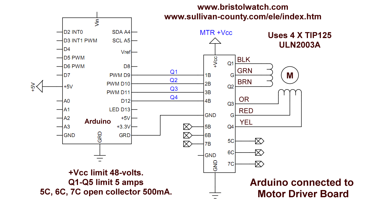
Fig. 2 Electrical connections Arduino with unipolar stepper driver control board.
Stepper motor and Arduino connections. The board has seven inputs. Four are used to drive ULN2003A inputs to drive the power transistors.
The remaining three of seven ULN2003A drivers are bought out to header pins. These are open-collector rated at 50-volts at 500mA.
Note the stepper motor connections must be connected as shown. Other motors with different colors are a matter of trial-error.
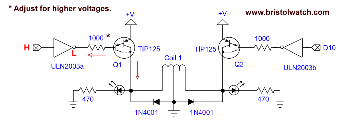
Fig. 3 TIP125 driver pair diagram for each stepper winding.
The electrical connections to each stepper motor winding uses a pair of transistors.
A HIGH input switches the ULN2003A driver to ground. The creates an emitter-base current turning the collector-emitter current to drive the load.
The TIP125 has internal suppressor diodes from collector-emitter and I added 1N4001 diodes as shown.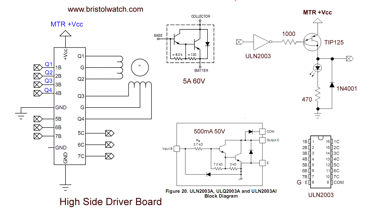
Fig. 4 various parts used in unipolar stepper motor board.
Internal parts of the driver board.
Note the motor supply voltage was passed through a constant current source set to 1 amp.
Code
The code was written originally for a 12-volt Airpax stepper motor. It consists of two subroutines forward(count, step_delay) and reverse(count, step_delay).
It consists of a sequence of 4-bit stepper out bits turning ON-OFF the various halves of each coil.
The forward or clockwise subroutine is stepped through an infinite while loop. Each step decrement a variable "count" that breaks the loop at count = 0.
Reverse or counter-clockwise is the same the sequence is reversed.
One can use direct port commands or a string of digitalWrite() commands, four per step.
See Arduino Port Registers Revisited.
The winding are switched all off before the next 4-bits are written.
The stepper motor webpage goes more into how stepper motors operate. See Using a Unipolar Stepper Motor with a Arduino.
- Related to above:
- Using a Unipolar Stepper Motor with a Arduino
- ULN2003A Darlington Transistor Array with Circuit Examples
- Tutorial Using TIP120 and TIP125 Power Darlington Transistors
- YouTube
- ULN2003A Transistor Array with Arduino
- Arduino Stepper Motor Control
- Using the TIP120 & TIP125 Darlington Transistors with Arduino
The new code is as follows original code on the Arduino stepper motor page.
/*
  Hall sensor on Airpax blue supply, brown grnd, gray signal
  stepper motor demo for pf35t-48 and 55mod48 and airpax
  Q1 - Black
  Q2 - Brown
  Q3 - Orange
  Q4 - Yellow
  In this example we are using Digital pins 9,10,11, 12 with Q1 = digital pin 9.
*/


#define CW 2
#define CCW 3

//Using Meneba 23LM-304-26
#define black 9 // Q1 - Green stripe
#define brown 10 // Q2 - Green
#define orange 11 // Q3 - Red
#define yellow 12 // Q4 - Red Stripe

void setup()  {
  // Serial.begin(9600);
  DDRB = 0x3f; // Digital pins 8-13 output
  pinMode(CW, INPUT);
  pinMode(CCW, INPUT);

  digitalWrite(CW, 1);
  digitalWrite(CCW, 1);
  PORTB = PORTB & B11100001;  // all outputs to stepper off
}


void loop() {

  forward(46, 10);
  delay(1000);

  reverse(46, 10);
  delay(1000);

  forward(200, 10);
  delay(1000);

  reverse(200, 10);
  delay(1000);

} // end loop


void forward(int count, int j) {

  int i = 0;
  j = j + 5;
  while (1)   {

    // digitalWrite(black, 1);
    // digitalWrite(brown, 0);
    // digitalWrite(orange, 1);
    // digitalWrite(yellow, 0);

    PORTB = PORTB & B11100001;  // all outputs to stepper off
    PORTB = PORTB | B11101011;  // OR new value
    delay(j);
    i++;
    if (i >= count) break;

    //  digitalWrite(black, 0);
    //  digitalWrite(brown, 1);
    //  digitalWrite(orange, 1);
    //   digitalWrite(yellow, 0);

    PORTB = PORTB & B11100001;  // all outputs to stepper off
    PORTB = PORTB | B11101101;  // OR new value
    delay(j);
    i++;
    if (i >= count) break;


    //   digitalWrite(black, 0);
    //   digitalWrite(brown, 1);
    //   digitalWrite(orange, 0);
    //   digitalWrite(yellow, 1);

    PORTB = PORTB & B11100001;  // all outputs to stepper off
    PORTB = PORTB | B11110100;  // OR new value
    delay(j);
    i++;
    if (i >= count) break;


    //   digitalWrite(black, 1);
    //   digitalWrite(brown, 0);
    //  digitalWrite(orange, 0);
    //  digitalWrite(yellow, 1);

    PORTB = PORTB & B11100001;  // all outputs to stepper off
    PORTB = PORTB | B11110011;  // OR new value
    delay(j);
    i++;
    if (i >= count) break;


  }

  PORTB = PORTB & B11100001;  // all outputs to stepper off

}

//////////////////////////////////////////

void reverse(int count, int j) {

  int i = 0;
  j = j + 5;
  while (1)   {

    //  digitalWrite(black, 1);
    //   digitalWrite(brown, 0);
    //  digitalWrite(orange, 0);
    //  digitalWrite(yellow, 1);

    PORTB = PORTB & B11100001;  // all outputs to stepper off
    PORTB = PORTB | B11110011;  // OR new value
    delay(j);
    i++;
    if (i >= count) break;

    //   digitalWrite(black, 0);
    //  digitalWrite(brown, 1);
    //  digitalWrite(orange, 0);
    //  digitalWrite(yellow, 1);

    PORTB = PORTB & B11100001;  // all outputs to stepper off
    PORTB = PORTB | B11110101;  // OR new value
    delay(j);
    i++;
    if (i >= count) break;

    //  digitalWrite(black, 0);
    //  digitalWrite(brown, 1);
    //   digitalWrite(orange, 1);
    //   digitalWrite(yellow, 0);

    PORTB = PORTB & B11100001;  // all outputs to stepper off
    PORTB = PORTB | B11101101;  // OR new value
    delay(j);
    i++;
    if (i >= count) break;

    //  digitalWrite(black, 1);
    //  digitalWrite(brown, 0);
    //  digitalWrite(orange, 1);
    //  digitalWrite(yellow, 0);

    PORTB = PORTB & B11100001;  // all outputs to stepper off
    PORTB = PORTB | B11101011;  // OR new value
    delay(j);
    i++;
    if (i >= count) break;

  }

  PORTB = PORTB & B11100001; // all outputs to stepper off

}
Date: 7-11-2021
- Constant Current Source Theory Testing
- Arduino Measures Current from Constant Current Source
- Review Ohm's Law for Trouble-Shooting CCS Circuits
- Arduino Power Magnetic Driver Board for Stepper Motors
- Arduino Controlled Power Constant Current Source
Related video to above:
- Constant Current Source Multimeter Trouble Shooting
- Ohm's Law Review for Constant Current Source
- Arduino Unipolar Stepper Motor Driver Board with Arduino Code
- Arduino Controlled Constant Current Source
- Comparator Circuits:
- Comparator Theory Circuits Tutorial
- Comparator Hysteresis and Schmitt Triggers
- Voltage Comparator Information And Circuits
- Looking at Window Comparator Circuits
- Opto-Coupler SCR and Triac Circuits:
- Improved AC Zero Crossing Detectors for Arduino
- Zero-Crossing Detectors Circuits and Applications
- Basic Triacs and SCRs
- Solid State AC Relays with Triacs
- Light Activated Silicon Controlled Rectifier (LASCR)
- Light Activated SCR Based Optocouplers Circuit Examples
- Comparing Photo Triac, Photo SCR Opto-Couplers
- Silicon Controlled Rectifier Review and Circuits
- Silicon Controlled Rectifiers Connected as Power Triacs