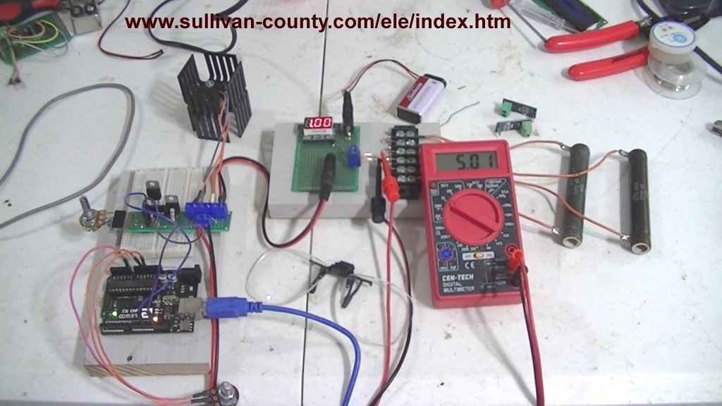
Fig. 1 Test setup Arduino controlled constant current source.
Arduino Controlled Power Constant Current Source
by Lewis Loflin
Note: click on any image for larger view.
Adding a single switching transistor enables microcontroller control of the output. Current limit can also be set.
For more on the original constant current source see Constant Current Source Theory Testing.
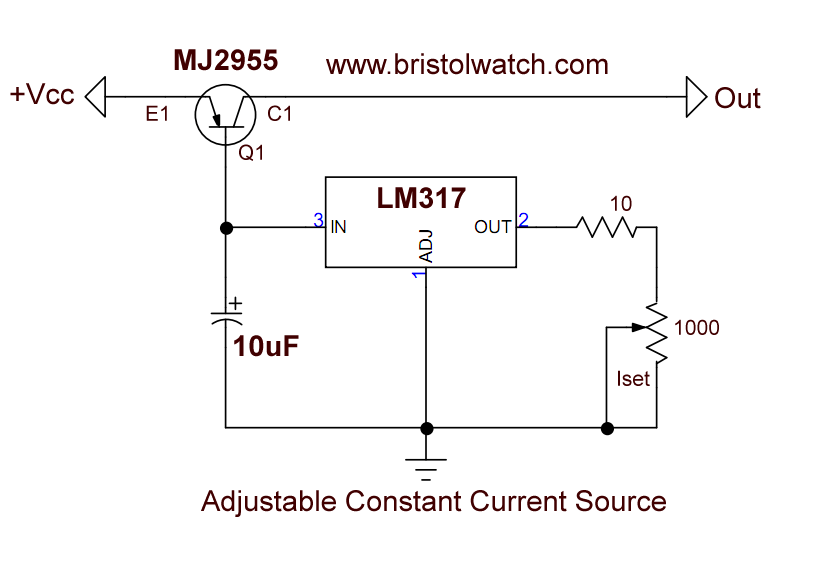
Fig. 2 Original variable constant current source circuit using LM317.
The original CCS circuit is shown in Fig. 2. The LM317 circuit sets the emitter-base current. This controls the emitter-collector current through Q1.
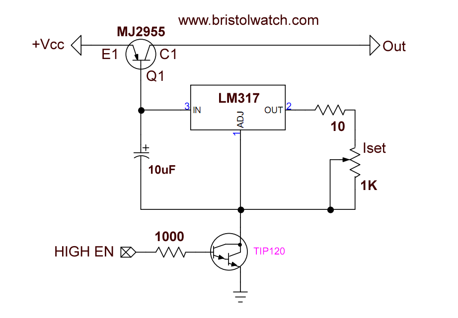
Fig. 3 Switching transistor in ground side LM317 constant current source.
By adding a TIP120 transistor to the ground circuit enable an Arduino to switch the circuit ON-OFF. This also enables the use of pulse-width-modulation to control the output.
Iset now determines maximum current while Arduino or other microcontroller controls overall power output.
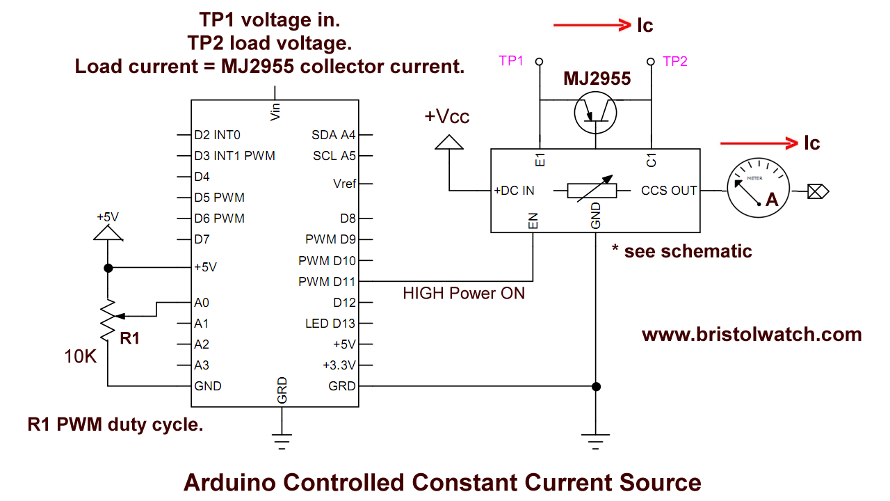
Fig. 4 Wiring diagram Arduino controlled constant current source.
Fig. 4 is the circuit used in the demo video.
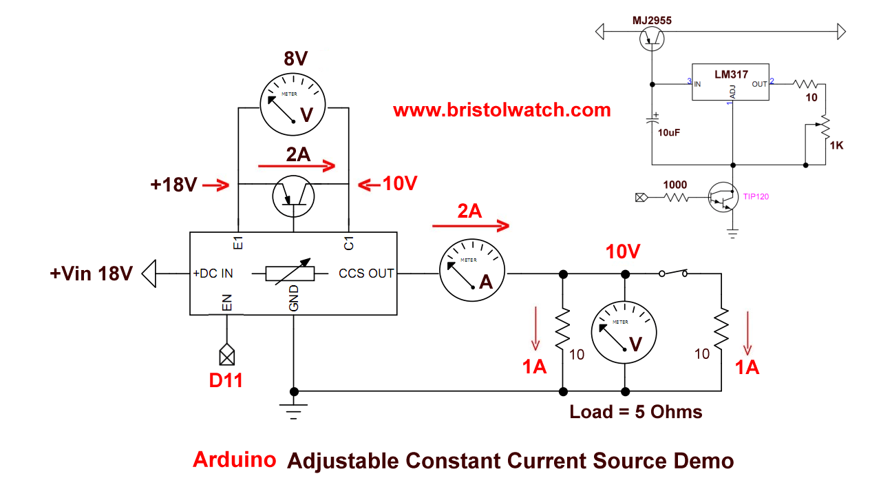
Fig. 5 Electrical test schematic Arduino controlled variable constant current source.
Fig. 5 are the load connections in the test circuit.
Code
#define pwmPin 11

int val;
void setup() {
  // put your setup code here, to run once:
  digitalWrite(pwmPin, 0);
}

void loop() {
  // put your main code here, to run repeatedly:
  val = analogRead(0) / 4;
  analogWrite(pwmPin, val);
  delay(100);
}
Date: 7-11-2021
- Constant Current Source Theory Testing
- Arduino Measures Current from Constant Current Source
- Review Ohm's Law for Trouble-Shooting CCS Circuits
- Arduino Power Magnetic Driver Board for Stepper Motors
- Arduino Controlled Power Constant Current Source
Related video to above:
- Constant Current Source Multimeter Trouble Shooting
- Ohm's Law Review for Constant Current Source
- Arduino Unipolar Stepper Motor Driver Board with Arduino Code
- Arduino Controlled Constant Current Source
- Related to above:
- Using a Unipolar Stepper Motor with a Arduino
- ULN2003A Darlington Transistor Array with Circuit Examples
- Tutorial Using TIP120 and TIP125 Power Darlington Transistors
- YouTube
- ULN2003A Transistor Array with Arduino
- Arduino Stepper Motor Control
- Using the TIP120 & TIP125 Darlington Transistors with Arduino
- Constant Current Circuits with LM317, LM334, etc.
- Experiments with TL431 Shunt Regulator
- TL431 Precision Current Regulator Circuits
- TL431 Based Current Limiter Constant Current Source Circuits
- TL431 Shunt Regulator Circuits
- Simple Triac-SCR Test Lab for You Tube
- Constant Current Circuits with the LM334
- LM334 CCS Circuits with Thermistors, Photocells
- LM317 High Power Constant Current Source Circuit
- LM317 Constant Current Source Circuits
- LM317 Adjustable Voltage Source Current Boost
- LM317 Constant Current Source for Lighting LEDs
- 3 Amp LM741 Op-Amp Constant Current Source